
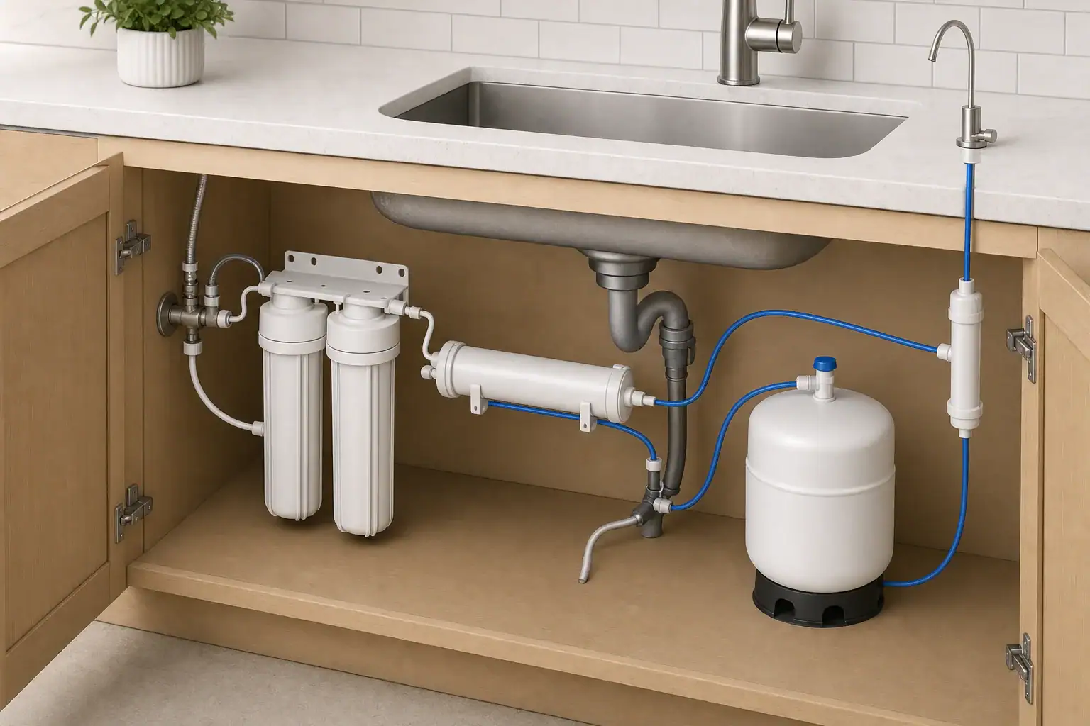
Quick answer: Reverse osmosis uses pressure to move prefiltered water across a semipermeable membrane. The membrane creates two streams at once: permeate, which goes to storage or dispensing, and concentrate, which carries rejected material to the drain. Feed pressure, water conditions, restrictions, and tank backpressure affect how quickly permeate is made.
How does reverse osmosis work?
Reverse osmosis (RO) is a pressure-driven separation process. Cold feed water is routed through pretreatment components and into a membrane housing. Pressure on the feed side drives part of the water through the membrane as permeate. Water that remains on the feed side exits as concentrate, also called reject water or brine, and normally goes to a drain.
That means an RO membrane has two outlets during production—not one. The U.S. Environmental Protection Agency (EPA) describes RO as a process that produces treated permeate and a concentrate stream from pressurized water passing across a semipermeable membrane. EPA’s point-of-use RO overview also notes that systems vary by design.
A membrane is selective, but it is not accurate to say that it passes only water molecules or that every RO system produces absolutely pure water. Specific contaminant-reduction claims depend on the exact system, its configuration, and its current certification or performance documentation.
Pressure is what makes permeate flow
Osmosis is the natural movement of water across a selective membrane in response to a concentration difference. Reverse osmosis applies pressure to the feed-water side to drive water in the opposite direction: through the membrane and into the permeate passage.
What matters is the usable pressure difference across the membrane, not merely the pressure measured at the cold-water supply. Pressure in the permeate path works against production. In a conventional system, a filling storage tank adds backpressure, leaving less effective driving pressure for new permeate. The University of Nevada, Reno identifies pressure difference, membrane construction, and membrane surface area as key factors affecting RO flow in its residential RO explanation.
For a broader explanation of why pressure and delivered flow are not the same thing, see water pressure vs. flow rate.
Follow the flow through a conventional RO system
Many under-sink RO systems use a pressurized storage tank. The precise order of cartridges, valves, and tubing differs by model, so use the system’s installation manual and flow diagram to identify a particular unit. A typical path looks like this.
1. Cold water enters prefilters
Water first enters from the cold-water supply. Systems may use sediment filtration, carbon filtration, or both before the membrane. These components condition the incoming water and add some resistance to the path. A restricted, improperly installed, or unsuitable replacement cartridge can reduce the pressure available farther downstream.
2. Pressurized feed water reaches the RO membrane
Inside the membrane housing, feed water travels along the membrane surface. Part becomes permeate by crossing the membrane; the rest continues through the housing as concentrate. These streams are produced simultaneously while the system is making water.
3. Concentrate travels to the drain
The concentrate outlet commonly passes through a manufacturer-designed flow-control arrangement before reaching the household drain. This path is part of normal RO operation: it provides an exit for water and rejected material that do not become permeate.
For example, Pentair’s RO-2550 installation and operation manual shows product water traveling toward a storage tank while reject water is routed to the drain. That manual documents its own system layout; it should not be used to assume the same drain ratio, controls, or maintenance needs for another RO unit.
4. Permeate fills the storage tank
In a conventional system, permeate usually enters a pressurized storage tank rather than flowing straight from the membrane to the faucet. When the drinking-water faucet is opened, pressure in the tank pushes stored water through the dispensing line.
As the tank fills, its backpressure rises and permeate production slows. EPA’s WaterSense supporting statement for point-of-use RO systems explains that rising tank backpressure reduces permeate production and that treatment and reject flow stop when the system reaches its shutoff condition. For a model-specific tank check, see RO tank pressure: how to check and adjust it safely.
5. The automatic shutoff closes the feed path
Many tank systems use an automatic shutoff valve that responds to pressures on the feed and permeate sides. When the tank reaches the design’s shutoff condition, the valve closes the incoming feed path. Normal membrane production and normal concentrate flow then stop. The valve arrangement and shutoff point are model-specific.
If a tank system continues sending water to the drain after it should have shut off, do not cap or bypass its drain line. Compare its behavior with the manufacturer’s documentation first. Our guide to RO automatic-shutoff valve symptoms covers that separate troubleshooting task.
6. Stored water goes through the dispensing path
Opening the dedicated drinking-water faucet releases water from the tank. Many systems include a postfilter between the tank and faucet, but the presence, location, and purpose of that component vary. Confirm the flow path from the exact model’s manual rather than relying on a generic “number of stages.”
RO flow path at a glance
| Component | What enters | What leaves | Pressure role | What you may notice |
|---|---|---|---|---|
| Prefilters | Cold feed water | Pretreated feed water | Add resistance before the membrane | A restriction may coincide with slower production |
| RO membrane | Pressurized pretreated water | Permeate and concentrate | Feed-side pressure drives permeate production | Drain flow can occur while the system makes water |
| Flow control and drain line | Concentrate | Household drain | Helps maintain the manufacturer’s intended membrane conditions | Compare unusual behavior with the model manual |
| Storage tank | Permeate | Stored permeate | Rising tank pressure opposes additional production | Refilling slows as the tank approaches its shutoff condition |
| Automatic shutoff | Feed and permeate pressure signals | Closed feed path at shutoff | Stops normal production and drain flow | A tank system should eventually stop producing water |
| Postfilter and faucet | Tank water or direct tankless permeate | Dispensed water | Uses tank pressure or a pump-assisted path | A tankless unit may operate a pump while dispensing |
Why does reverse osmosis send water to a drain?
An RO membrane does not hold all rejected material inside a sealed cartridge. Feed water flows along one side of the membrane, while the concentrate stream carries away the portion that did not become permeate. The drain connection is therefore an expected part of the separation process during active production.
Drain flow alone is not proof of a plumbing leak. However, a conventional tank system that never stops producing or draining needs model-specific diagnosis. Do not alter a flow restrictor or disconnect the drain path to stop the sound of draining; those parts affect how the membrane operates. For efficiency and ratio questions, see RO waste-water ratio: what is normal and how to reduce it.
What controls RO production speed?
There is no universal production rate for residential RO. A listed membrane or system rate is tied to stated test conditions, which may differ from conditions at a particular sink. The following factors can affect real-world production:
- Usable feed pressure: Within the manufacturer’s operating limits, more effective pressure across the membrane generally supports more permeate production.
- Tank backpressure: In a conventional system, production slows as the storage tank fills.
- Water temperature: Colder feed water can reduce production compared with a system’s rated conditions.
- Feed-water concentration: Water composition affects the pressure relationship across the membrane.
- Membrane design and area: These are part of a membrane’s designed capacity.
- Restrictions: Loaded prefilters, membrane fouling, kinked tubing, or other restricted passages can limit water movement.
Pentair lists low water temperature, elevated feed-water concentration, plugged prefilters, membrane fouling, and tubing restrictions among possible causes of low product flow in its PRF-RO manual. Those are useful diagnostic categories, not a diagnosis for every system. If flow has dropped, use the exact system manual and a structured low-RO-flow troubleshooting checklist.
How tankless RO flow differs
Tankless RO uses the same core membrane separation: pressurized feed water becomes permeate and concentrate. The main difference is that permeate does not first collect in a conventional pressurized storage tank.
Instead, a tankless unit delivers permeate toward the faucet as water is requested. Many tankless designs use an electric pump and electronic controls, but their internal routing and operating sequence are not identical. As one documented example, Pentair’s QuickConnect tankless RO manual shows an internal pump, a product-water connection to the drinking faucet, and a separate reject-water drain connection.
That example establishes the layout for that product, not every tankless RO system. For a purchase-focused comparison, see tank vs. tankless RO.
Use the manual to trace your own RO system
A system diagram is more reliable than assumptions based on the number of cartridges or housings. Before changing a component or diagnosing unusual flow, check the current manual for:
- Feed-water, permeate, storage-tank, faucet, and drain connections
- Whether the system has a storage tank, pump, or both
- Its approved pressure and temperature operating boundaries
- The test conditions behind its stated production rate
- The location and type of concentrate flow control
- How the automatic shutoff is intended to operate
- The approved replacement membrane and cartridges
What an RO certification claim can tell you
NSF/ANSI 58 applies to reverse-osmosis drinking-water treatment systems, but the standard number by itself does not establish every possible contaminant-reduction claim. NSF states that total dissolved solids reduction is required under NSF/ANSI 58, while other reduction claims are optional and must be evaluated for the particular product.
Check the exact model, replacement modules, and claimed reductions in the current NSF/ANSI 58 product listings. A stage count, taste, odor, clarity, or a TDS-meter reading is not by itself proof that water is safe or that a specific contaminant claim applies. For more detail, read NSF/ANSI 58 explained and what reverse osmosis removes and what it does not.
Frequently asked questions
Does an RO system make water whenever the faucet is open?
Not necessarily. In a conventional tank system, the faucet usually draws from stored permeate, while the membrane refills the tank afterward. A tankless system can produce water toward the faucet on demand, but its pump and controls are model-specific.
Is water going to the RO drain normal?
Drain flow is normally expected while an RO system is producing permeate because concentrate must leave the membrane housing. A system that continues draining after a conventional tank should have shut off should be checked against its manual rather than modified.
Why does a full RO tank refill more slowly near the end?
As the storage tank fills, its pressure rises. That backpressure reduces the effective pressure difference available to drive permeate across the membrane, so production slows until the shutoff mechanism stops the feed path.
The practical way to understand any RO unit is to follow its documented route: cold feed to pretreatment, pretreatment to membrane, concentrate to drain, and permeate either to a storage branch or directly toward a tankless dispensing path.
- NSF/ANSI standards explained (42/53/401/58)
- Clear trade-offs: pitcher vs faucet vs under-sink vs RO
- Maintenance planning: cost per gallon and replacement cadence