
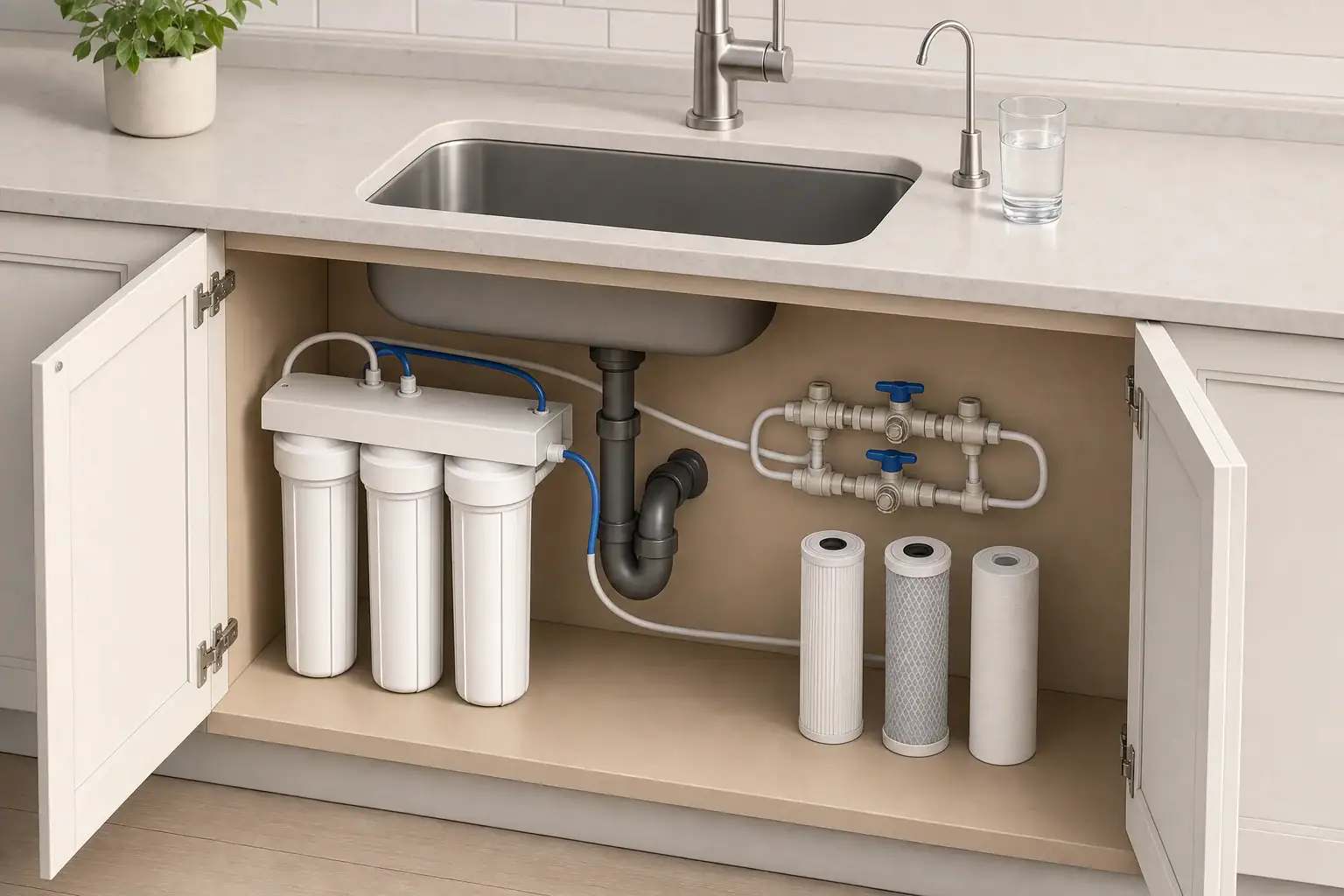
A bypass valve allows water to travel around a whole-house filter instead of through it. That sounds like a minor plumbing feature, but its location and configuration affect maintenance, pressure troubleshooting, leak isolation, and whether the home can continue receiving water while the equipment is offline.
The term bypass may refer to a control built into a filter head or to an external arrangement of pipes and valves. These designs can serve the same basic purpose, but they do not always provide the same service access or isolation. Understanding the layout helps homeowners evaluate a new installation and operate an existing system more safely.
What a Whole-House Filter Bypass Valve Does
During normal operation, incoming water enters the treatment equipment, passes through the filter media or cartridges, and returns to the home’s distribution plumbing. When the system is in bypass, water follows a separate path around some or all of that equipment.
A bypass can be useful when:
- A cartridge, tank, seal, or control valve needs service.
- A leaking filter housing must be isolated until it can be repaired.
- Pressure loss needs to be compared with and without the filter online.
- Water service must remain available during scheduled maintenance.
Water supplied in bypass is generally untreated by the equipment being bypassed. It may still be suitable for ordinary household use depending on the source water and the reason treatment was installed, but it should not be assumed to have the same characteristics as filtered water.
A bypass is also different from a shutoff. A shutoff stops flow, while a true bypass redirects it. Two isolation valves without a connecting bypass pipe can separate the filter from the plumbing, but they cannot keep the house supplied through that section.
Why the Plumbing Layout Matters
A practical bypass layout must provide a complete alternate route from the supply side to the house side. It should also allow the treatment equipment to be isolated without unintentionally creating a second open flow path.
Valve placement determines what can be serviced. A bypass around one sediment housing does not necessarily bypass a downstream carbon tank, ultraviolet unit, softener, or other treatment stage. Likewise, a bypass around an entire treatment assembly may not allow one component to be serviced while the others remain online. Whole house filters and water softeners have different jobs, which can affect which equipment needs separate service access.
Pipe diameter, valve type, fittings, and the number of direction changes also affect resistance to flow. A narrow bypass line may deliver noticeably less water than the normal plumbing route, particularly when several fixtures operate at once. Full-port valves and appropriately sized piping generally reduce avoidable restrictions, although actual sizing depends on household demand and local plumbing requirements.
Example values for illustration.
| Layout | Typical use | Main consideration |
|---|---|---|
| Integrated filter-head bypass | Single tank or control head | Compact, but may not isolate external connections |
| External three-valve bypass | Single filter or treatment assembly | Provides a visible alternate route when arranged correctly |
| Isolation valves only | Equipment removal where water can be shut off | Does not maintain downstream service |
| System-wide bypass | Several treatment stages in series | All stages are taken offline together |
| Individual-stage bypasses | Systems requiring separate service access | Uses more pipe, valves, and wall space |
| Parallel treatment trains | Specialized high-flow or continuous-service designs | More complex balancing and maintenance |
| No permanent bypass | Simple installations where shutdowns are acceptable | House water may need to remain off during service |
Common Bypass Configurations
Integrated bypass controls
Some whole-house treatment heads have a built-in bypass mechanism. This can reduce the number of external fittings and make routine service straightforward. However, the control may isolate only the equipment attached to that head. It may not isolate prefilters, gauges, ultraviolet equipment, or plumbing connections installed nearby.
The operating position should be clearly identifiable without forcing the control. If the position is uncertain, the equipment documentation or a qualified service professional should be consulted.
External three-valve layouts
A traditional external arrangement uses one valve on the filter inlet, one on the outlet, and one on a bridge pipe connecting the upstream and downstream sides. In normal service, water is directed through the filter and the bridge remains closed. In bypass mode, the filter is isolated and the bridge provides the alternate path.
This arrangement is easy to understand visually, but valve sequence matters. Opening or closing valves carelessly can interrupt service, release pressure unexpectedly, or allow water to flow in an unintended direction. Valves should be operated according to the system design rather than by assumption.
Multiple treatment stages
A home may have a sediment filter followed by carbon treatment, scale control, ultraviolet treatment, or other equipment. A single bypass around the entire assembly is simple, while separate bypasses offer more service flexibility. The appropriate choice depends on whether individual stages can safely and usefully remain online when another stage is unavailable.
Flow Rate and Pressure Drop Through the Layout
Every filter, valve, elbow, and pipe section creates some resistance. The effect is usually most noticeable during peak demand, such as when showers, laundry, and outdoor fixtures run at the same time.
Static pressure is measured when no water is flowing. Dynamic pressure is measured during use. A filter restriction may not be obvious from a static reading because pressure loss increases as flow rises. Comparing upstream and downstream dynamic pressure at a repeatable flow can provide more useful information.
Important planning factors include:
- The expected peak household flow rate rather than only average use.
- The service flow capability of the filter media or cartridge.
- Pipe and valve inside diameter.
- Pressure available from the municipal supply or well system.
- Pressure needed by fixtures and downstream treatment equipment.
A bypass should not be treated as a way to compensate for an undersized filter. If pressure improves greatly in bypass, the filter may be clogged, undersized, incorrectly installed, or operating beyond its intended flow range. Whole-house filter flow-rate sizing can help put the comparison in context. The bypass comparison is a diagnostic clue, not a complete diagnosis.
Planning a Serviceable and Code-Compliant Installation
A useful layout leaves enough room to reach valves, remove housings, replace cartridges, and inspect connections. A valve hidden behind a tank or mounted too close to a wall may technically exist but remain difficult to operate during a leak.
Planning should also account for:
- A main shutoff that remains accessible.
- Support for heavy filter housings and water-filled piping.
- Clearance below cartridge housings for removal.
- Protection from freezing, impact, and excessive heat.
- A safe method for relieving trapped pressure before service.
- Drainage or leak containment appropriate to the installation area.
- Local requirements for backflow protection, pipe materials, and bonding.
Check valves, pressure-reducing valves, thermal expansion controls, and well pressure equipment can affect how pressure behaves when valves are operated. These devices should not be removed, defeated, or bypassed casually. Plumbing changes should follow local code and may require a licensed plumber or permit.
It is also important to identify whether untreated bypass water could create a practical problem. For example, bypassing equipment used to address known sediment, staining, taste, odor, or other source-water concerns may be acceptable only for limited uses or a limited period. The decision should reflect current water testing and the purpose of each treatment stage.
Maintenance and Bypass Troubleshooting
Valves that remain untouched for years may become stiff or develop seal problems. They can be checked periodically using the equipment manufacturer’s maintenance guidance, but they should not be forced. Labels or a simple plumbing diagram stored near the equipment can help household members and service technicians understand the intended flow path.
After maintenance, trapped air may cause temporary sputtering or cloudy-looking water. Flow should be restored gradually according to the equipment instructions so housings and media are not exposed to a sudden pressure surge. Leaks should be checked at filter heads, unions, drains, valve stems, and housing seals.
If pressure is poor in both normal and bypass modes, the restriction may be elsewhere. Possible causes include a partially closed main valve, supply-pressure changes, a pressure regulator issue, undersized plumbing, a well-system problem, or restrictions downstream from the filter.
If pressure is poor only when the filter is online, useful checks include cartridge age, sediment loading, media condition, control-valve position, and whether the installed system is sized for actual peak demand. Troubleshooting whole-house low pressure after installation can help identify other likely causes. Pressure readings are most meaningful when taken at similar flow rates.
Example values for illustration.
| Operating condition | Upstream reading | Downstream reading | Possible interpretation |
|---|---|---|---|
| No water flowing | 60 psi | 60 psi | Static readings alone do not show flow restriction |
| Moderate flow through filter | 55 psi | 51 psi | Small pressure difference under this test condition |
| Peak flow through filter | 50 psi | 40 psi | Higher demand produces a larger pressure drop |
| Moderate flow with loaded cartridge | 55 psi | 43 psi | Cartridge condition may warrant evaluation |
| Moderate flow in bypass | 55 psi | 53 psi | Shows the approximate non-filter plumbing loss |
| Low incoming supply pressure | 38 psi | 35 psi | The filter may not be the primary cause |
Related guides:
Installing a Whole House Filter: Placement, Bypass, and Leak Prevention •
Whole House Filter Flow Rate: Sizing by GPM and Household Count •
Whole House Filter Maintenance Calendar: Monthly & Yearly Checklist •
Troubleshooting Whole House Low Pressure After Install
Questions to Ask When Evaluating a Bypass Layout
A clear plumbing diagram is more informative than the presence of a valve labeled bypass. Homeowners evaluating an installation can ask:
- Does the bypass route around one component or the entire treatment system?
- Can the equipment be fully isolated and depressurized for service?
- Will the house continue receiving water while the filter is offline?
- Is the bypass pipe large enough for expected household demand?
- Are all valves accessible and is their normal position clear?
- What type of untreated water will reach the home during bypass?
- Do downstream devices require filtered water or minimum pressure?
The best layout is one that matches the treatment purpose, available pressure, peak flow, service needs, and local plumbing rules. A bypass is most useful when its flow path is understood before maintenance or an unexpected leak occurs.
Frequently asked questions
Do I need a bypass valve for a whole-house water filter?
A bypass is not required in every installation, but it can keep water available during filter service or help isolate a leak. Without one, the home may need to be shut off while the filter is serviced.
What is the correct valve position for a three-valve filter bypass?
In normal operation, the inlet and outlet valves to the filter are typically open and the bypass bridge valve is closed. In bypass mode, the filter valves are closed and the bridge valve is open, but the system’s diagram or instructions should control.
Will water pressure increase when a whole-house filter is in bypass?
It may increase if the filter or its plumbing is creating significant restriction. If pressure remains low in bypass, the cause may be elsewhere in the supply or distribution plumbing.
Can I use water while the filter is bypassed?
Usually, the plumbing can continue supplying water if the bypass route is properly installed. However, the water will not receive treatment from the bypassed equipment, so consider the purpose of that treatment before extended use.
Can a built-in filter bypass isolate the entire treatment system?
Not always. An integrated bypass may apply only to the filter head or tank it is attached to. Separate prefilters, ultraviolet units, gauges, and nearby connections may still require external isolation valves.
- NSF/ANSI standards explained (42/53/401/58)
- Clear trade-offs: pitcher vs faucet vs under-sink vs RO
- Maintenance planning: cost per gallon and replacement cadence